1. INITIAL SETUP:
Open project in SIMATIC MANAGER. Go to Options >> Set PG/PC interface in SIMATIC MANAGER main screen. Set PLCSIM.TCPIP.1 as parameter and click OK button.

A warning message may appear about access path changing.

Click OK button.
2. WORKING WITH PLCSIM:
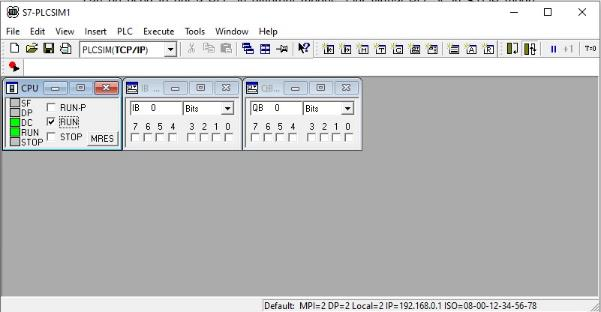
Open SIMATIC MANAGER main window. Go to Options >> Simulate Modules. A PLCSIM window will open as shown in below picture.

This tool will be used to simulate and test the program. It will work like virtual PLC. User can perform all the operation in this tool which can be performed with actual PLC hardware. PLCSIM main window contains a default small window named as CPU. LEDs on left side in particular window represents different status LEDs available in actual PLC. Check box like RUN, STOP etc. represents the switch on hardware which can be used to put a PLC in different modes. Our virtual PLC is in STOP mode according to above image which means PLC will not work i.e. it will not accept/generate any input/output even if power supply is given and PLC is loaded with correct program. It will appear like a dead hardware.
Now go to Insert >> Input Variables. A new small window will appear. This window represents the inputs feed into PLC using different input modules. This window can be used to feed inputs into PLC too. Now go to Insert >> Output Variables. Again a new small window will appear which represents different outputs generated by PLC. This window can be used to monitor the outputs generated by different PLC output modules.
Now go to SIMATIC MANAGER and follow the steps for downloading program into PLC explained in previous chapter. This procedure will download program into our virtual PLC as we have selected PLCSIM as parameter in PG/PC interface.
Click on RUN check box in CPU window. Now virtual PLC will work in RUN mode i.e. it will work according to program downloaded into CPU. PLCSIM window will look like below image.
Now we need to test our program. For that focus on a small window next to CPU window. Here “IB 0” represents the inputs assigned to address byte 0. “Bits” is selected next to IB 0 which means we will be able to feed bit wise inputs into PLC i.e. digital inputs. Different numbers with check box are given below that which represents different digital inputs available on DI module. Click on checkbox given below number 0 which represents 24 V DC input feed into input 0 of DI module i.e. push button input in our program.

We can see that check box below number 0 in next window (QB 0) turns ON automatically which is due to logic written in our program. That means our logic for digital input is working correctly.

Now we will check the analog logic. For that write “PIW 288” in place of “IB 0” as we have assigned that particular hardware address for analog input. Hit enter key.

Now write “PQW 304” in place of “QB 0” in next small window and hit enter key.
Enter any random decimal number in a text box below “PIW 288” and hit enter key.

Same number appears automatically in next window which means same analog output is generated by PLC as entered in analog input module i.e. our logic for analog input is working correctly.
Same way any program can be tested using PLCSIM.
3. TROUBLESHOOTING:
If inputs/outputs are not working according to program then there may be problem in logic. User can check real time working of logic by running the program in monitor mode. For that open particular FB or OB which you want to run in monitor mode and click on Monitor icon shown in below image.

You can see networks turned into green color. Various variables can be seen working according to their current actual value.

Actual value of analog variables can also be seen. If value is not easy to understand then you can change the representation by right clicking on particular value and going to Representation.
If logic is not working correctly and program is required to be modified then turn off the monitor mode, modify program, download again into PLC and then again run the same program into monitor mode to check it’s working.
If there is any problem in hardware then it can also be monitored. For that open the hardware window and click on online icon as shown in below picture.

Hardware will run into online mode. Right click on the CPU name in rack and click on Module information to check current state of CPU. Different CPU related information can be seen by selecting different tabs.

Select diagnostic buffer tab to watch the logs and activities performed in CPU.

Same method can be used with actual physical PLC set to troubleshoot and monitor the program.