1. Getting started
On your computer desktop locate the menu.
Start>Programs>Rockwell_Software>RSLogix500 English>RSLogix 500 English.
Click to open the program.

Creating a project

● Select the series of PLC
3. Save Project

● Click “File” Menu
● Select “Save As”
● Type “MicroEconomix LAB1” in the “File name” box
● Click “Save”
4. Creating the 1st Rung of Ladder Logic
Program this 1st rung:

a) Add an Input Instruction

● Click, hold the left mouse button and drag the XIC(examine if closed) button onto the left side of the rung you just created. When you see a green box, release the mouse button.
● With the instruction highlighted Type I:0/0 [Enter]. This is the address of the XIC (examine if closed) instruction.
b) Add Output Instruction
● Click, hold the left mouse button and drag the OTE (output energized) button onto the right side of the rung you just created.
● When you see a green box, release the mouse button.
● With the instruction highlighted Type O:0/0 [Enter]. This is the address of the OTE instruction.

5. Creating the 2nd Rung of Logic

a) Create a New Rung
Click, hold the left mouse button and drag the “New Rung” button over rung “0001”.
When you see a green box, release the mouse button.
b) Add the 1st Input Instruction
Click, hold the left mouse button and drag the XIO (examine if open) button onto the left side of the rung you just created. When you see a green box, release the mouse button.
6. Verify your work
If Program has errors
● To find the errors in the program click on the error message in the “Verify results window” the error is then highlighted in the ladder window.
● Fix the error and run “Verify file” again.
● When all the errors are fixed you can then save and download the program.
7. Documenting your Program
● Click on the Input I:0/0 to highlight
● Right mouse on I:0/0 and select “Edit Description- I:0/0”
● Select “Address”
● Type “Input Switch 0” in the Edit window
● Select “OK”

● Click on the Output O:0/0 to highlight
● Right mouse on O:0/0 and select “Edit Description- O:0/0”
● Select “Address”
● Type “Output 0” in the Edit window
● Select “OK”

8. Save your work

9. Download the Program
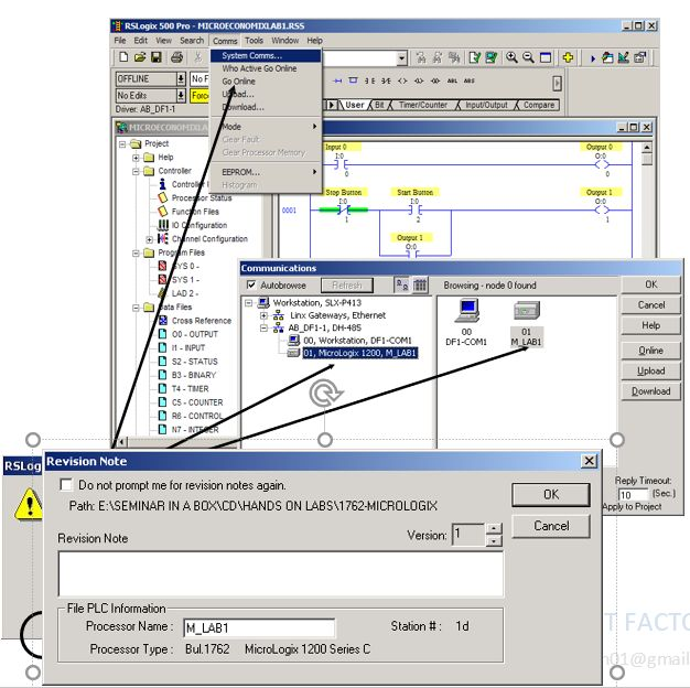
● Select the menu item “Comms > System Comms”
● Three primary selections
● “Online” Establish the “path”
● “Upload” Receive from the controller
● “Download” Send to the controller
● Highlight the device at Node 01.
● Select “Download
● Select “OK” in the Revision note window. The revision note box is used to keep track of changes made to the existing program. You can create many revisions of the same program. This feature can be disabled if desired.
● Select “Yes” to download your program over the existing program that resides in the processor. This window will appear whenever a program is being downloaded to the processor.
● Download verification window will appear when the download takes place.
10. Put the Micro into the RUN mode

Select “Yes” to go online. This will allow you to monitor the program that now resides in the processor.
● Click on the down arrow next to the word REMOTE PROG
● Three Run selections
● One scan cycle with outputs disabled
● Select “Run”
● Select “Yes” for “Are you sure window”
11. Monitor the Controller

● With the controller in “Remote Run”, you can monitor or edit data within the controller.
● This allows:
● Program debugging
● Change data variables while in run When “Green” bars are shown on either side of logic elements, this indicates “Logical Continuity”, this helps to determine how the application is operating.
● This design is to help in debugging an application’s logic.