
Mitsubishi PLC series
FX PLC SERIES
- FX-1S PLC
- FX-1N PLC
- FX-2N PLC
- FX-3U PLC

- FX-3G PLC
- FX5U PLC
Mitsubishi PLC wiring configuration

PLC and their programming software
| PLC | Software |
| Q series | GT developer |
| FX series | GX works2 |
| FX5U | GX Works3 |
Mitsubishi communication protocols
- USB cable
- Ethernet
Addressing for ladder logic programming
Input (X) : Inputs are designed to give commands and data from external devices,
e.g. pushbuttons, select switches, etc., to the PLC
Output (Y): Outputs are used to provide the control results of a program from the PLC to external devices, e.g. solenoids, signal lamps
Internal relays (M): Internal relays are auxiliary relays used in a CPU module and not latched
Latch relays (L) : Latch relays are auxiliary relays used in a CPU module and
latched (backed up at power failure)

● Addressing of inputs and outputs is in Octal (X0-X7, X10-X17)
● Addressing for both inputs and outputs start at 0 (X0 and Y0)
● Addressing is consecutive
● If input/output powered extension units/blocks have been connected when the power is turned on, the main unit automatically assigns the input/output numbers (X/Y) (octal) to the units/blocks.
● Therefore, it is unnecessary to specify the input/output numbers with parameters.
Digital signal programming

We have chosen FX3U PLC in which digital inputs start from X00, X01, X02, X03, X04, X05, X07, X10, X11….
And outputs start from Y00, Y01,Y02,Y03,Y04,Y05,Y06,Y07,Y10,Y11…
Rising / Falling pulse instructions
- Rising pulse
![]()
● True for one scan on up transition at address
● Operating a lamp from a push button
● When a push button is pressed the first time a lamp will glow. When a push button is pressed a second time a lamp will turn off.

- Falling pulse
![]()
● True for one scan on the down transition at address
Use of a timer


Use of counter

● It is also an output instruction
● Counter is retentive
● Reset instruction is used to reset it
● 16/32 bit counters available
● Understand the following:
● –Preset: Constants or Register
● –Accumulator: Current status of the counter, use the address of Counter Device
● –Contact or Done bit: Can be accessed using the address of Counter Device

Direction control M8### for C###
For C200 , M8200 is used to control the direction

Math instructions

Compare instructions
● Instruction compares two data and results in a true or false condition
● It can be used with other sequence instructions
● All instructions are input instructions except CMP which is an output instruction
● Compare instructions are available to compare
16-bit data
32-bit data
INLINE comparisons


The data of S1 is compared to the data of S2. The result is indicated by 3 bit devices specified from the head address entered as D.
The bit devices indicate:
–S2 is less than S1 – bit device D is ON
–S2 is equal to S1 – bit device D+1 is ON
–S2 is greater than S1 – bit device D+2 is ON
Try other variations like DCMP
CP Instruction
● A single data value (S) is compared against a data range (S1-S2)
● S is less than S1, bit device D is ON
● S is equal to or between S1 and S2 – bit device D+1 is ON
● S is greater than S2 – bit device D+2 is ON
Move, jump, and logical instructions
- Move instruction


Analog signals
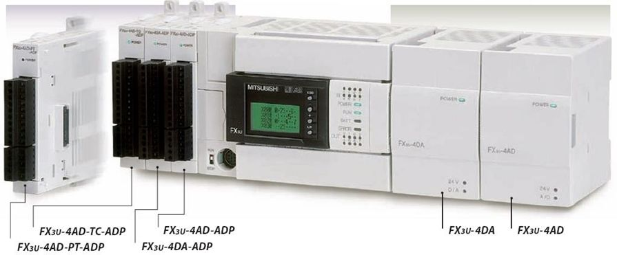
Two types:
● Special Adapter (Left hand side )
● Special Function modules (Right Hand Side)
- Special Adapter
● Always connected on left side of PLC
● Up to four no. of adapter can be connected
● The expansion board is needed to connect the special adapter
● To use the high-speed input/output special adapter, be sure to connect the high-speed input/output special adapter first, and then connect the analog special adapter
● No need to use the traditional To/From instructions to configure and operate.
● The input analog data will be converted into digital data and then stored in the special devices of the FX Series PLC.
● The number of averaging time and the input mode to be specified
● Special auxiliary relays (10 points) and special data registers (10 points) are assigned starting from the adapter nearest the main unit
● Analog special adapter nearest the main unit is counted as the 1st adapter, and the next adapter as the 2nd adapter, and so on
● Do not include the high speed input/output special adapter and the communication special adapter
Input characteristics
| Voltage Input
|
Current Input
|
|
| Resolution
|
2.5mV (10V/4000)
|
10µA (16mA/1600)
|
| Conversion time
|
200 micro sec per channel | The data will be updated every scan time |
| Input Characteristics |  |
 |
FX3U-4AD-ADP

● It is a four channels analog input adapter
● Current or voltage inputs or combination of both.
● Up to four Adapter (including analog outputs also) can be used with FX 3U PLC as shown.
● Converted data of each channel will be automatically written in the special
data register of the FX3U/FX3UC Series PLC.
Assignment of data registers and bit devices are as shown.

Analog sensors’ wiring with FX3U-4AD-ADP adapter

| Device | Function | Status |
| M8260 | Input mode of channel 1; ON=Current Input, OFF=Voltage Input | Read / Write |
| M8261 | Input mode of channel 2; ON=Current Input, OFF=Voltage Input | Read / Write |
| M8262 | Input mode of channel 3; ON=Current Input, OFF=Voltage Input | Read / Write |
| M8263 | Input mode of channel 4; ON=Current Input, OFF=Voltage Input | Read / Write |
| D8260 | Channel-1 input data | Read |
| D8261 | Channel-2 input data | Read |
| D8262 | Channel-3 input data | Read |
| D8263 | Channel-4 input data | Read |
| D8264 | Number of averaging time for channel-1 (Setting range: 1 to 4095) | Read / Write |
| D8265 | Number of averaging time for channel-2 (Setting range: 1 to 4095) | Read / Write |
| D8266 | Number of averaging time for channel-3 (Setting range: 1 to 4095) | Read / Write |
| D8267 | Number of averaging time for channel-4 (Setting range: 1 to 4095) | Read / Write |
| D8268 | Error status | Read / Write |
| D8269 | Model code | Read |
Example

- Special fuction module

● The FX2N-8AD analog input block converts 8 points of analog input values into digital values and transfers them to the PLC.
● Connect the special function block to the right side of the FX3U Series PLC
● Up to 8 special function blocks can be connected
● To/From instructions are required to interface
Wiring

Program

Other instructions
- Zone Reset Instruction :ZRST
● It is used to reset a range of addresses.
● The arguments can be bit or word devices

- Master Control Instruction
● It is an output instruction
● It activates or deactivates the execution of a group or zone of ladder rungs
● Nesting pointer is used with MC
● Nesting Range: N0 to N7
● Third argument is bit device which is turned on if MC is enabled
● It is always followed with MCR instruction
● MCR ends the zone or group of rungs